Communication ECA Phase IV Class 7: Roaming Vehicles 20181024

This lesson will focus on arrays and how they can be used to control the actions of the students’ wheeled robots. Students will discover what arrays are, how they work, and why they are important in computer programming. They will also learn how to incorporate an array into their program.

The students are going to program their robot to move according to a recorded set of instructions given to it through the buttons on the EV3 Brick according to these parameters:

Program 1: Recording One Action to Make the Robot Move

  1. Start the program.
  2. Create a Variable Block called “Drive”.
  3. Wait for a Brick Button to be bumped.
  4. Play sound “Click 2”.
  5. Record the numerical value of the pressed button in the variable “Drive”.
  6. Wait for 2 seconds.
  7. Play sound “G02”.
  8. Read the number stored in variable “Drive” and send the value to a switch.
  9. Numeric switch:
  10. If Drive = 1, curve turn the robot left.
  11. If Drive = 3, curve turn the robot right.
  12. If Drive = 4, move the robot straight forward for 2 rotations of the wheels.
  13. If Drive = 5, move the robot straight backward for 2 rotations of the wheels.
  14. Play sound “Game Over 2”.

Program 2: Recording Several Actions to Make the Robot Move (Optional)

The students will use the “array operations” and “Variable” blocks to realize a function to first recording several actions and then drive the robot.

In an Array Operations Block, record the button press in the Value parameter, loop number in the Index parameter and variable name in the Array parameter. Write all the information from the Array Operations Block into the “drive” Variable Block.

Communication ECA Phase IV Class 6: Cruise Control 20181017

During this lesson, the students gain a good understanding of the Variable Block. The students will use this information to create a cruise control feature for their wheeled robots. The students will utilize two Touch Sensors to control and maintain the speed of their robot. The students will need to program their robot so that, once moving, it can be sped up by pressing the Touch Sensor. Code blocks for controlling the Touch Sensor (wait) should be placed inside a loop.

The Variable Block is a programming block that can store data (text, logic, a numeric, or arrays), which can be overwritten at any time while the program is running. This block has to be read and then written to, using the Math, Text, or Array Operations Blocks.

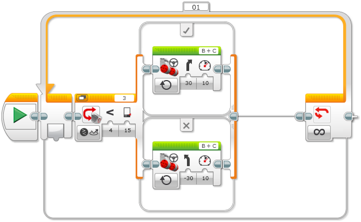
Program 1: Increase Speed with Variable

  1. Start the program.
  2. Create a Variable Block called “Speed” and enter a value of 0.
  3. If the Touch Sensor is pressed:
    1. Read the variable called “Speed”
    2. Add 10 to the read value
    3. Write the result in the variable called “Speed”
    4. Read the variable called “Speed”
    5. Start motors B and C at a speed set to the value stored in the variable called “Speed”
  4. ELSE
  5. (Do nothing)
  6. Repeat steps 3a to 3e forever.

Program 2: Increase and Decrease Speed with Variable

With the first program written and the robot accelerating when the Touch Sensor is pressed, the students would extend the program to slow the robot down.

One solution could be to have a second unlimited loop similar to the loop used in the first programming exercise. This loop would use a different Touch Sensor port (another sensor added). The Math Block would be changed to subtract rather than add.

  1. Start the program.
  2. Create a Variable Block called “Speed”, enter a value of 0, and start two tasks.

TASK 1

  1. If Touch Sensor 1 is pressed:
  2. Read the variable called “Speed”
  3. Add 10 to the read value
  4. Write the result in the variable called “Speed”
  5. Read the variable called “Speed”
  6. Start motors B and C at a speed set to the value stored in the variable called “Speed”

ELSE

(Do nothing)

  1. Repeat steps 3a to 3e forever.

TASK 2

  1. If Touch Sensor 2 is pressed:
  2. Read the variable called “Speed”
  3. Subtract 10 from the read value
  4. Write the result in the variable called “Speed”
  5. Read the variable called “Speed”
  6. Start motors B and C at a speed set to the value stored in the variable called “Speed”

ELSE

(Do nothing)

  1. Repeat steps 5a to 5e forever.**

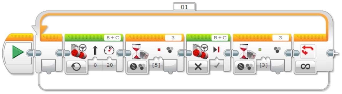
Program 3: Increase and Decrease Speed with Variable and Display

With the wheeled robot now accelerating and decelerating at the touch of a button (or two), students can extend their programming to show how fast their robots are moving. Students will use the Display Block to show this value in the Variable Block.

A new skill to be learned in this lesson is the creation of a My Block. Two of these can be seen in the solution below. My Blocks allow users to create subroutines of programs they have already written. In the case below, we have taken the acceleration and deceleration loops and created My Blocks from these programs. There are two reasons to do this: first to save space, and second to allow these subroutines to be reused in other programs.

  1. Start the program.
  2. Create a Variable Block called “Speed”, enter a value of 0, and start three tasks.

TASK 1

  1. Start My Block “Acceleration”.

TASK 2

  1. Start My Block “Deceleration”.

TASK 3

  1. Read the variable called “Speed”.
  2. Display the value stored in the variable called “Speed”.
  3. Repeat steps 5 and 6 forever.

Communication ECA Phase IV Class 5: Traffic Lights Detection and Point Turn 20181010

In this Lesson Part I, students will use the Color Sensor to make their wheeled robot move more autonomously in order to simulate how an autonomous car might respond to traffic lights. In Part II, the students’ mission is to program your robot to complete a point turn to an exact angle by using the Gyro Sensor.

Program 1: Red Light Detection

  1. Start the program.
  2. Start motors B and C (drive forward).
  3. Wait for the Color Sensor to detect the color red.
  4. Stop the motors.

Program 2: Turn your robot clockwise for 45 degrees

Rotating using a wheel is not very precise. If you try to turn your robot in the dust or on a slippery surface, it may not reach the right angle. What the Gyro Sensor does is to help you make much more precise movements.

  1. Move Tank
  2. Wait – Gyro Sensor – Compare Angle – Type [3] (Greater Than or Equal), Degrees [45]
  3. Move Tank – Off

Program 3: Red and Green Light Detection Loop

The “Loop” block will be used.

  1. Start the program.
  2. Start motors B and C (drive forward).
  3. Wait for the Color Sensor to detect the color red.
  4. Stop the motors.
  5. Wait for the Color Sensor to detect the color green.
  6. Repeat steps 2 to 5 forever.

Program 4: Line Following in Loop (Optional)

The students will create an automated, driverless vehicle that can follow a line. They will explore how an automated vehicle might be guided along a road or track. The “switch” block will be used, which works very similar to the “time” block who can control almost all sensors. The program will work best using black or blue tape on a very light (or white) surface.

  1. Start the program.
  2. Start motors B and C (drive forward with a curve toward the line).
  3. Wait for the Color Sensor to detect the color black.
  4. Start motors B and C (drive forward with a curve away from the line).
  5. Wait for the Color Sensor to detect the color white.
  6. Repeat steps 2 to 5 forever.

Communication ECA Phase IV Class 4: Driving Reversely 20181003

In this Lesson, students will use the Brick Status Light and Display Block to program their wheeled robot to simulate visual signals for pedestrians, other car drivers, and passengers when reversing. Students will also use the Touch Sensor to simulate forward and reverse gears. Touch Sensor can detect when the sensor’s red button has been pressed or released.

Program 1: Bump and Reverse
There are three different modes of the Touch Sensor, i.e., pressed, released, bumped (Pressed and Released Just Before).

  1. Start the Program.
  2. Drive forward in a straight line at the desired speed.
  3. Wait for the Touch Sensor (simulating changing to reverse gear) to be “bumped”.
  4. Stop the motors.
  5. Wait for 1 second.
  6. Activate the “reverse lights” (amber lights on EV3 Brick).
  7. Reverse direction of travel for 2 seconds。

Program 2: Bump, Wait for Reverse Gear

Introduce the use of the button on the EV3 Brick to act as the “reverse” gear.

  1. Start the program.
  2. Drive forward in a straight line at the desired speed.
  3. Wait for the Touch Sensor (simulating change to reverse gear) to be “bumped”.
  4. Stop the motors.
  5. Wait for the Brick Button (simulating change to reverse gear) to be pressed.
  6. Activate the “reverse lights” (amber lights on the EV3 Brick).
  7. Reverse the direction of travel for 2 seconds.

Communication ECA Phase IV Class 3: Automatic Parking 20180926

In this class, we will achieve an autonomous parking. Frist, we construct the Robot Educator base model, which is a basic wheeled robot.
Program 1: Three Point Turn

1. Start the Program
2. Turn the driving base and stop after 1.5 seconds.
3. Turn the driving base left and stop after 1 second.
4. Move the driving base forward for 3 seconds.

Program 2: Parallel Parking

1. Start the Program.
2. Drive forward in a straight line at the desired speed.
3. Wait for 1 second.
4. Reverse motor rotation while turning for 1.5 rotation.
5. Reverse motor rotation while turning the other way for 1.5 rotation.
6. Drive backward in a straight line for 0.5 rotation.
7. Drive forward in a straight line for 1 rotation.

Program 3: Parallel Parking with Simulating Reverse Gear and Reverse Warning lights

1. Start the Program.
2. Drive forward in a straight line at the desired speed.
3. Wait for 1 second.
4. Turn light on (reverse light).
5. Reverse motor rotation while turning for 1.5 rotation.
6. Reverse motor rotation while turning the other way for 1.5 rotation.
7. Drive backward in a straight line for 0.5 rotation.
8. Drive forward in a straight line for 1 rotation.

After finishing each program, make sure to check the following building before sending command to the wheeled robot: Are the wires correctly connected from the motors to ports B and C? Are the wheels correctly installed? Are the wheels rotating freely?

Communication ECA Phase IV Class 2: Programming Basics 20180919

In the second class, we continued talking the main programming blocks in the EV3 software and the hardware communications. The programming blocks include three categories: Action, Flow control, and Sensors. The Action includes all action related blocks such as the motor, motion mode, and sound and light of the brick. The Flow control includes start, delay, loop, and switch blocks. The Sensors include color sensors, ultrasonic sensors, gyroscope sensors, and touch sensors.

The first program we covered was the motor control.

The program starts by a “start” block in the “flow control” category, follows by a “large motor” block in the “action” category, then a “wait” block in the “flow control” category. The differences among three motor control blocks come from the first button, from where we can choose the control mode of the motor. The five control modes are literally intuitive. The second button controls the power input, the number can be both positive and negative, which can make the motor rotate and clockwise contraclockwise.  The third one depends on the choice of the first control mode. For example, in the first “large motor” block, we picked “on for rotations”, power to “50”, and “1”. The block controlled the motor to rotate 1 clockwise circle. The “wait” block is nothing but to control the motor to stop for 1 sec.

The second program we did was the touch sensor.

As the last program, it starts by a “start” block in the “flow control” category, follows by a “wait” block in the “flow control” category, then a “sound” block in the “action” category. The “wait” block is very powerful and can be used to control all sensors by choosing from the first button list. The reason we used a “wait” block instead of the “touch sensor” in the “sensor” category is that the program pipeline needs to be paused until the sensor get triggered after a time delay. Due to the fact that the time is not determined until the sensor gets triggered, thus we cannot use set a determined time as same as the first motor control program. The “sound” block was activated when the touch sensor was triggered and gave a sound “Ouch”, which can be picked in the upper right button list.

Communication ECA Phase IV Class 1: Programming Introduction 20180912

Phase IV is the most advanced level of Play2Learn Education Lego Challenge Program. In the next 8 weeks, different robotics programming classes using different sensors including color sensors, ultrasonic sensors, gyroscope sensors, and touch sensors will be covered.

The first class was the introduction to hardware and the software of the Lego EV3 kit. The hardware talked in the first introductory class including the central controller, i.e. the brick, the big and medium motors, color sensors, ultrasonic sensors, gyroscope sensors, and touch sensors. The basic functionality of these parts was detailed during the class. The software, which is the programming interface on the computer used to control and communicate with all the above hardware parts was also introduced.

After went through the basic of the hardware and the software, we guided students to rename the names of their bricks, and then to connect bricks to their laptop through Bluetooth. The student achieved a significant step after the first class. In the second class, we are going to introduce and practice the basic programming skills.

Communication ECA Phase III Class 7: Pneumatic: Robot Hand 20180418

Today we built a robot hand, which was a more complex application of the pneumatic system. The pneumatic robot hand composed pneumatic components from cylinders and pumps to the air valve, the air tank, and the manometer. With the built model, the students got a deeper understanding of the design philosophy and working principles of the pneumatic system, which built a solid ground for the next following even more advanced pneumatic robot arm model.

The STEM information behind this section is the application of pneumatic systems as well as the cylinder piston rod force output calculation, which can be calculated by multiplying the air pressure with the piston area. All the students finished the model and the experiments. And they conducted the objects grabbing with a lot of interests and fun.

Communication ECA Phase II Class 7: The Dogbot 20180418

The project we built today is the Dogbot. A Dogbot uses many mechanical mechanisms including Belt drives, gear drives, cam drives, levers, and linkages. Two students built the model as a group, then they conducted experiments by using different settings for cam drives, levers structures, and belt drives. The cam drives, levers structures, and belt drives (pulley structures) control the dogbot’s eye motion, the dogbot’s jaw motion, and the dogbot’s tail motion respectively. The STEM information behind this section are the motion transition mechanical mechanisms including belt, gears, and linkages. These are the key components composing the motion transition system of almost all existing mechatronics products in our daily lives.

All students finished the model and experiments with a lot of fun. They enjoyed the class and understand deeper of the key physics concepts behind these important mechanical mechanisms.

Communication ECA Phase III Class 6: Pneumatics: Scissor Lift 20180411

The theme of today is scissor lift. The scissor model composes pneumatic components including cylinders, pumps, air valves, air tanks, and manometers. In the process of building models and conducting tests, the students got a deeper understanding of the design philosophy and working principles of the pneumatic system, which built a solid ground for the next following more advanced pneumatic application models. This section is a good illustration of the air storage system in the pneumatic system.

The STEM information behind this section is the application of pneumatic systems. The cylinder piston rod output forces can be calculated by multiplying the air pressure to the piston area. All the students finished the model and the experiments. They are ready for the next more advanced pneumatic systems.

Play2Learn Education